SAFETY INSTRUCTIONS
WARNING - Read all safety warnings and instructions. Failure to follow warnings and instructions may result in electric shock, fire and / or serious injury. Keep all warnings and instructions for future reference.
1. SAFETY OF THE WORK AREA
- Keep the work area clean and well lit. Messy or dark areas are prone to accidents.
- Do not operate power tools in explosive atmospheres, for example in the presence of flammable liquids, gases or dust. Power tools produce sparks that can ignite dusts or fumes.
- Keep children and others away while using the tool. Distractions can make you lose control of the tool.
2. SECURITY OF PERSONS
- Stay alert, watch what you are doing and use common sense in your use of the tool. Do not use a tool while fatigued or under the influence of drugs, alcohol or medication. A moment of inattention while using a tool can result in serious personal injury.
- Use safety equipment. Always wear eye protection. Safety equipment such as dust masks, non-skid safety shoes, helmets or hearing protection used for the proper conditions will reduce personal injury.
- Do not rush. Keep a suitable position and balance at all times. This allows better control of the tool in unexpected situations.
- Dress appropriately. Do not wear loose clothing or jewelry. Keep hair, clothing and gloves away from moving parts. Loose clothes, jewelry or long hair can be caught in moving parts.
3. USE OF TOOLS OPERATING ON BATTERIES AND USE PRECAUTIONS
- Only recharge with the charger specified by the manufacturer. A charger that is suitable for one type of battery pack may create a fire hazard when used with another type of battery pack.
- When a battery pack is not in use, keep it away from other metal objects, such as paper clips, coins, keys, nails, screws, or other small objects that may result in a connection from one terminal to another. Shorting the terminals of a battery between them can cause burns or fire.
- In bad conditions, liquid can be ejected from the battery; avoid contact. In case of accidental contact, clean with water. If the liquid comes into contact with the eyes, seek additional medical help. Liquid ejected from the batteries may cause irritation or burns.
4. MAINTENANCE
- Have the tool serviced by a qualified service person using only identical replacement parts. This will ensure the safety of the tool.
Warning – When this symbol is displayed, safety measures are indicated to avoid possible dangers and damage.
Information – When this symbol is displayed, instructions for use are given for effective handling of the tool.
SAVE THIS INSTRUCTION MANUALfor consultation, training and transmission to any new user.
OVERVIEW
1. PRESENTATION
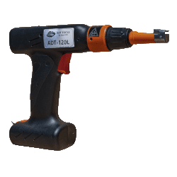
The cable tie tool is an exclusive cordless power tool that allows you to repeat tightening effortlessly with good control of the tightening torque and good repeatability while ensuring a perfect cut. All cable tie tools are equipped with a clamping head offering a setting of the effort but also the possibility of orienting the head in different directions.
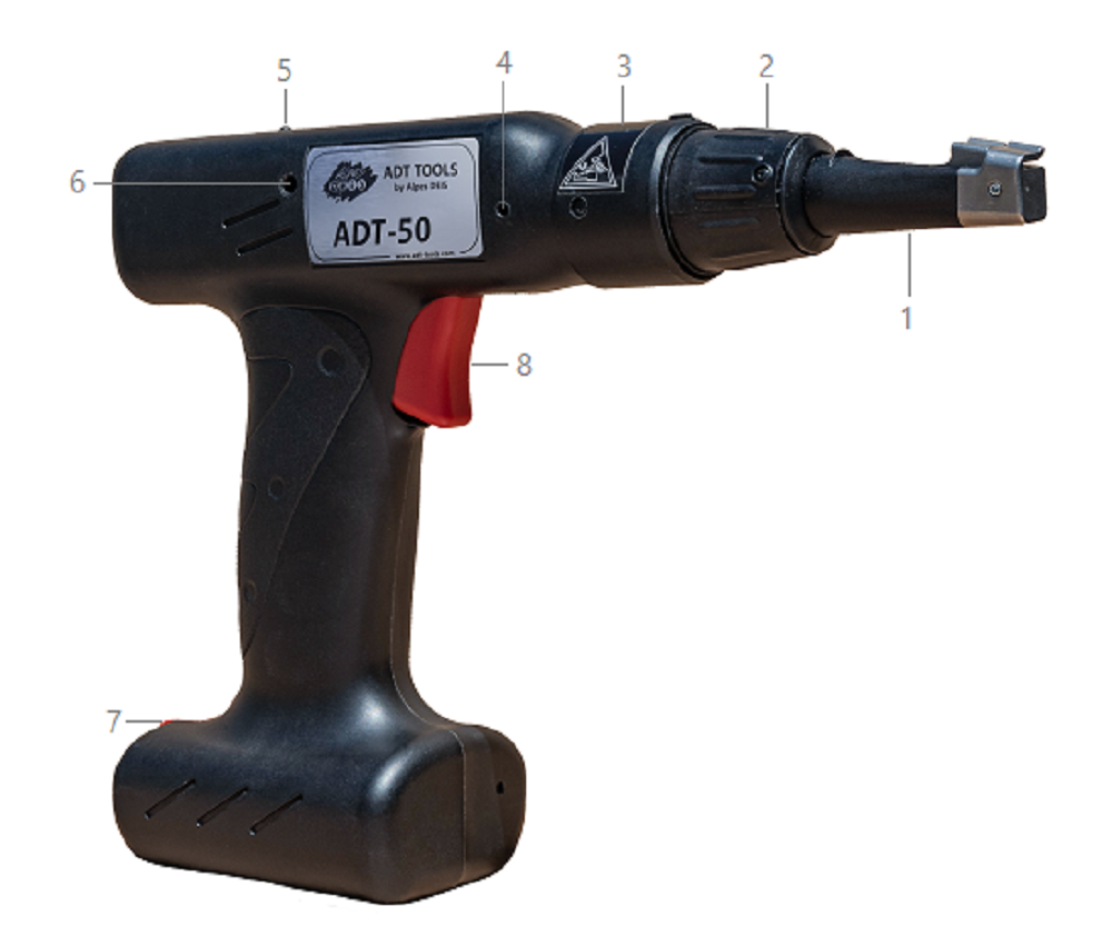
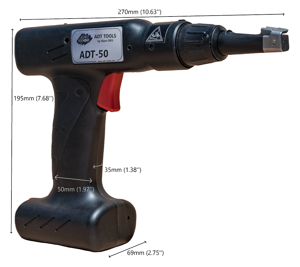
2. DESCRIPTION
1. Clamping head
2. Position adjustment wheel
3. Ring restricting access to the torque lock function
4. Opening for head replacement (for maintenance only)
5. Battery charge indicator light
6. Opening for suspension hook attachment
7. Battery locking clip
8. Trigger
In case of prolonged non-use, it is advisable to remove the battery from the tool and store it in a low humidity zone preferably between -4°F (-20 ° C) and +77°F (+ 25 ° C) max 122°F (+ 50 ° C).
3. MODELS
There are 3 models to cover a wide range of cable ties
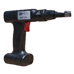
Tool for narrow cable ties (Black)
» L =2.5 à 4.7 mm (0.10’’ to 0,184’’)
» 8 clamping forces
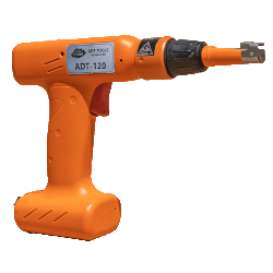
Tool for wide cable ties (Orange)
» L = 4.6 à 7.6 mm (0.189’’ to 0,299’’)
» 2 clamping forces
Tool for wide cable ties (Black & orange)
» L =4.6 à 7.6 mm (0.189’’ to 0,299’’)
» 8 clamping forces
ACCESSORIES
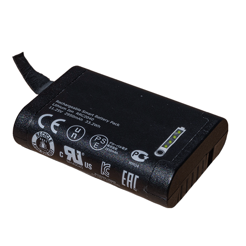
1. BATTERY
The cable tie tool is designed to work safely only with a battery pack RRC ref.2040-ADT with label below.
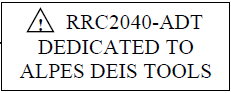
Sales reference for « Battery » : ADT-POW-01
Specifications:
- Voltage 10.80VDC
- Capacity 3.35Ah / 36.20Wh
Please consult the instructions for use of the battery to know the precautions for use of it.
2. CHARGER & AC ADAPTER
A standard charging station, compatible with the battery, is available for sale.
Compatible power supply included
Specifications Charger :
- Input voltage range charger 18-24V --- 4-3A
- Output voltage range charger 0-16.8V --- 0-4A
- Power 60W
Please consult the instructions of use of the charger to know the precautions of use of this one.
WARNING : If the power cable is damaged, it must be replaced by the manufacturer, its after-sales service or persons of similar qualification to avoid danger.
Sales reference for “Charger for battery + Power cord for AC adapter”:
- EU version: ADT-POW-02
- UK version: ADT-POW-03
- Australia version: ADT-POW-04
- US/CAN version: ADT-POW-05
- IT version: ADT-POW-06
- CH version: ADT-POW-07
- RU version: ADT-POW-08
- BR version: ADT-POW-09
3. FIXING HOOK OF SUSPENSION
In order to offer the user even more ease when handling the tool on a fixed station, a fixing hook of suspension is available to allow the user an even easier handling.
Sales reference «Fixing hook of suspension »: ADT-HOOK
4. HEAD MAINTENANCE KIT
This set is needed for maintenance on the cable tie tool. There are 3 versions corresponding to the different models:
- Sales reference Maintenance Kit ADT-50: ADT50-SPARE-10
- Sales reference Maintenance Kit ADT-120: ADT120-SPARE-10
- Sales reference Maintenance Kit ADT-120L: ADT120L-SPARE-10
A Maintenance Kit includes:
- 1 specific head with 1 blade already put inside
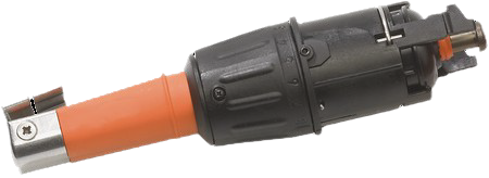
- 1 head removing tool

It is recommended to change the head every 100K cycles.
5. 20 SPARE CUTTING BLADES
This kit allows a frequent change of the blade to ensure a good and clean cut and to make the head and tool more durable. There are 3 versions corresponding to the different models:
- 20 Cutting blades for ADT-50: ADT50-SPARE-11
- 20 Cutting blades for ADT-120: ADT120-SPARE-11
- 20 Cutting blades for ADT-120L: ADT120L-SPARE-11
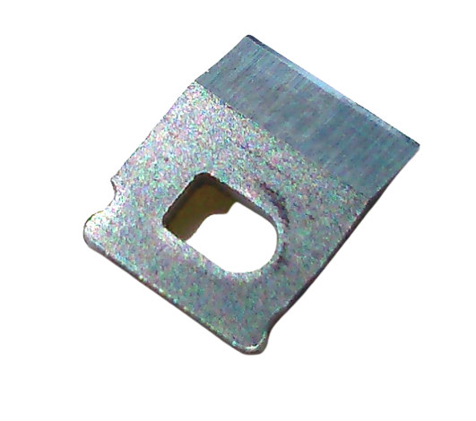
It is recommended to change the cutting blade every 30K cycles.
1. FIRST USE
Before first use, the battery must be charged to the supplied charger. Any other charger is strictly prohibited both on the functional aspect and on the security aspect.
Once the battery is charged, insert it in the housing of the tool provided for this. Take care of the direction of insertion. The cable tie tool is ready for use.
2. INSERT AND REMOVE BATTERY
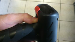
The images below describe the steps to take to insert the battery into the device.
1. Rotate the battery locking clip with your thumb to release the battery door entry.
2. Insert the battery but take care of direction of insertion.
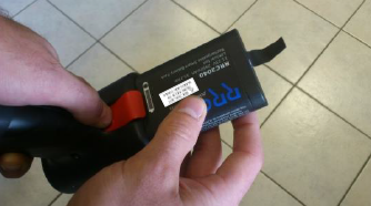
3. Slide the battery until it is fully engaged.
4. Release the battery locking clip.
Any attempt to remove the battery without pressing the battery locking clip will cause premature wear of the tab and an anticipated deterioration of it.
To remove the battery do it in the same way by press battery locking clip then pull the tab of the battery once the locking clip unlocked.
3. CLAMPING A CABLE TIE
3.1. CHOICE FOR TOOL
There are 3 models available:
- Cable tie tool ADT-50 for narrow cable ties 2,4-4,8 mm (0,09’’-0,18’’) width with low force
- Cable tie tool ADT-120 for wide cable ties 4,8-7,6 mm (0,18’’-0,30’’) width with high force
- Cable tie tool ADT-120L for wide cable ties 4,8-7,6 mm (0,18’’-0,30’’) width with low force
3.2. FORCE ADJUSTMENT FOR CABLE TIE
Position the head on the desired strength using the force adjustment ring.
Table of correspondence of positions by cable ties tool:
| Setting |
ADT-50 |
ADT-120 |
ADT-120L |
| Position 1 |
65 – 83 N
14.61 - 18.66 lbs |
175 - 250 N
39.34 - 56.20 lbs |
65 – 83 N
14.61 - 18.66 lbs |
| Position 2 |
81 – 107 N
18.21 - 24.05 lbs |
214 - 297 N
48.11 - 66.77 lbs |
81 – 107 N
18.21 - 24.05 lbs |
| Position 3 |
97 – 131 N
21.81 - 29.45 lbs |
Not allowed on this model of tool |
97 – 131 N
21.81 - 29.45 lbs |
| Position 4 |
113 – 151 N
25.40 - 33.95 lbs |
Not allowed on this model of tool |
113 – 151 N
25.40 - 33.95 lbs |
| Position 5 |
129 – 179 N
29.00 - 40.24 lbs |
Not allowed on this model of tool |
129 – 179 N
29.00 - 40.24 lbs |
| Position 6 |
145 – 203 N
32.60 - 45.64 lbs |
Not allowed on this model of tool |
145 – 203 N
32.60 - 45.64 lbs |
| Position 7 |
161 – 226 N
36.19 - 50.81 lbs |
Not allowed on this model of tool |
161 – 226 N
36.19 - 50.81 lbs |
| Position 8 |
175 – 250 N
39.34 - 56.20 lbs |
Not allowed on this model of tool |
175 – 250 N
39.34 - 56.20 lbs |
These ranges of torque are indicative. To know precisely the values of force of each tool, it is possible to ask a statement of verification.
After 100 000 cycles, it is advisable to change the head to maintain the forces and cutting quality capability.
When the force of the cable tie is not known, it is advisable to validate it by iteration by testing starting from the lowest position and gradually increasing.
The quality of a good tightening is defined when the cable tie set up can turn on itself but cannot translate on the support.
3.3. PERFORMING A TIGHTENING
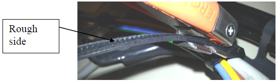
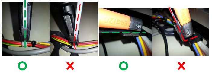
1. Once the cable tie manually tightened on the cable harness, put it in the head but prefer the rough side of the cable tie on the same side of head teeth. This precaution is not necessarily useful depending on the cable ties but is recommended for better control of the tightening.
Place the head of the tool at 45 ° angle to optimize insertion of the cable tie.
2. Press the trigger while holding the tool against the head of the cable tie and keeping a good alignment until cut the cable tie.
If the tightening was not enough, re press the trigger a second time to reach the force previously chosen and the automatic cut.
3. Once the cut is done, the cable tie waste is maintained as long as the trigger remains pressed.
4. Release the trigger to free the cable tie waste and to replace the head in standby position.
It is possible to free the cable tie waste without having to release the trigger.
5. Repeat the operation to perform a new clamping.
Never have finger, hand or person near the head when press the trigger to avoid potential hazards when tightening and cut.
3.4. LOCK THE TORQUE ADJUSTMENT
It is possible, if the user wishes, to lock the adjustment of the tightening torque to avoid using the clamp on an unwanted position. A locking screw is available on the head of the tool to perform this function.
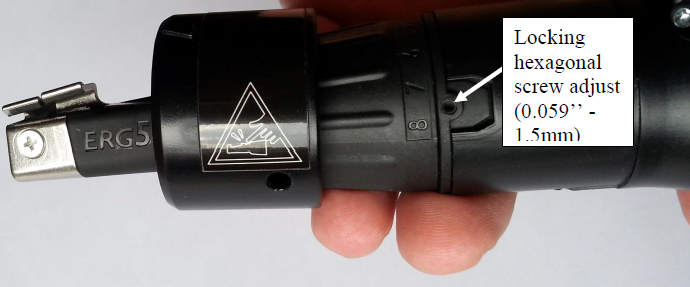
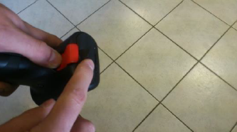
To access it, it is first necessary to remove the locking ring of the tool, as shown in the picture above.
To remove the locking ring of the tool:
- Press the locking pin with a screwdriver while pulling on the ring with your thumb.
Preferably use a torx screwdriver or other round tip.
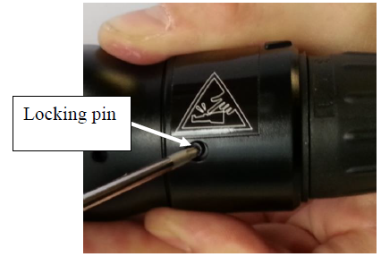
- Repeat the same operation on the locking pin located on the other side. The locking ring must be completely released then can be removed.
4. ENERGY LEVEL AND DISPLAY
4.1. ENERGY MANAGEMENT
To save battery power, in case of an unused tool more than 5 minutes, the tool goes into standby mode. The indicator light turns off.
The tool will wake up automatically when you press the trigger again.
In case of long time unused, it is advisable to remove the battery to avoid damaging it.
When using the tool, the light on the top of the tool indicates the battery charge level.
The mode mapping table for light is shown below:
| Colour |
Mode |
Description |
| Steady green |
Operationnal |
The clamp is in working order with a sufficient battery level. |
| Steady orange |
Alert |
The battery has reached 30% capacity. It has to be charged or replaced in the near future. |
| Steady red |
Run out |
The battery is in the critical zone (<10%) and needs to be charged immediately. The tool is no longer able to tighten the ties. A new battery must be installed. |
4.2. BATTERY CHANGE
Refer to paragraph 4 : Insert/Remove battery
- Rotate the battery locking clip with your thumb to release the battery door entry.
- Remove the discharged battery by pull the tab of the battery once the locking clip unlocked.
- Insert the charged battery but take care of direction of insertion.
- The tab should be facing up.
- Remove the battery locking clip.
REPAIR AND MAINTENANCE
1. TYPES OF DEFECT
The light also makes it possible to indicate to the user the possible malfunctions and security modes of the tool.
| Colour |
Mode |
Description |
| Blinking orange |
Temporary defect |
Overheating has been detected on the clamp. Operation is blocked until the tool has cooled down sufficiently. The system recovers its functionality as soon as the conditions that caused the lockout disappear. |
| Blinking red |
Prolonged defect |
A problem has been detected on the tool that prevents it from working properly. It is necessary to send the tool to the maintenance manager. |
| Blinking green |
Worn out battery |
When the battery is connected, a green flashing light for 5 seconds indicates that the battery in use is worn out (>500 charge/discharge cycles). It is still usable but will have reduced performance. |
2. LEVEL OF MAINTENANCE
Maintenance Level 1
When the blade or the head wears out, it is possible to carry out preventive maintenance called level 1 by personnel authorized to carry out maintenance and having read the maintenance manual.
This maintenance includes:
- The change of the head
- The regular change of blade to guarantee a perfect cut (a blade is available for about 30 000 cuts, this value strongly depends on the materials of cable ties)
Maintenance Level 2
Level 2 maintenance includes all other operations on this tool. It is provided exclusively by Alpes DEIS or an authorized distributor. The user is not allowed to open the tool for any intervention whatsoever.
Only authorized Alpes DEIS/distributor staff is authorized to effectuate any updates or repairs.
3. CUSTOMER SERVICE CONTACT INFORMATION :
- By email: adt-support@alpes-deis.fr
- Par mail:
Alpes DEIS
Service Tools
300, Rue des Techniques
74970 MARIGNIER
- By phone: +33 (0)4.50.89.24.00
4. SPARE PARTS
The following spare parts are available from the after-sales service:
- Battery: ADT-POW-01
- Battery charger with power cord:
- EU Version: ADT-POW-02
- UK Version: ADT-POW-03
- Australia Version: ADT-POW-04
- US/CAN Version: ADT-POW-05
- IT Version: ADT-POW-06
- CH Version: ADT-POW-07
- RU Version: ADT-POW-08
- BR Version: ADT-POW-09
- Maintenance Kit ADT-50: ADT50-SPARE-10
- Maintenance Kit ADT-120: ADT120-SPARE-10
- Maintenance Kit ADT-120L: ADT120L-SPARE-10
- 20 Cutting blades ADT-50: ADT50-SPARE-11
- 20 Cutting blades ADT-120: ADT120-SPARE-11
- 20 Cutting blades ADT-120L: ADT120L-SPARE-11
- Suspension hook: ADT-HOOK
- Documentation - Measurement certificate: ADT-CERT
1. SPECIFICATIONS
- Weight < 900g (2 lbs)
- Operating ambient temperature 5°C – 45°C (41°F – 113°F)
- Storage ambient temperature 0°C – 45°C (32°F – 113°F)
- Tightening torque (force) <= 300 N (67.44 lbs)
- Clamping speed 6 cycles/minute
Note : The tool is dimensioned to be able to tighten and cut a number of 6 cable ties per minute. More intensive use may cause the device to overheat and trigger overheating safety. Repetition of overheating can also cause accelerated aging of the device.
2. GUARANTEE
Alpes DEIS warrants this tool against all defects in material and workmanship for a period defined in the enclosed warranty card. During this period, Alpes DEIS will repair or replace, at its discretion, any defective product at no additional cost to its owner.
This warranty does not apply to any defect resulting from an accident, improper use, improper maintenance, or normal wear and tear.
3. DISPOSAL AND ECOLOGICAL CONCERNS
European Directive WEEE:
(Directive 2012/19/UE on Waste Electrical and Electronic Equipment)
This logo opposite indicates, in European Union, that the tool which you have just acquired must not be thrown with household waste. Indeed to allow the non-proliferation of hazardous materials in nature, the recovery and recycling of this product at the end of life, it is necessary:
- to deposit it in a waste station whose address is to ask the authorities of your city
- or return to your distributor
Thus the materials of this product will be treated to be upgraded and recycled at best for the preservation of natural resources and for the protection of human health. Thank you for your contribution.
For information the financing of the cost of this recycling is financed from the sale.
European Directive ROHS:
(Directive 2011/65/UE on Restriction Of Hazardous Substances of Electrical and Electronic Equipment)
This tool has been designed in compliance with this European directive setting the limits of hazardous substances in electrical and electronic equipment for the purpose of preserving natural resources and protecting human health.
4. CE REQUIREMENTS
This tool complies to European Directive named « Machines » 2006/42/CE (transposed into French law by decree n° 2008-1156 du 7 November 2008)
This tool complies to Safety European Directive 2006/95/CE
Mechanical and electrical hazards associated with power tools
This tool complies to EMC European Directive 2004/108/CE
Risks on Electromagnetic Compatibility
- Emission standard
- EN 55014-1:2007 + A1:2009+A2:2012
- EN 61000-6-3:2007+ A1:2011
- Immunity standard
- IEC 61000-4-2 :2008
- IEC 61000-4-3 :2010
- EN 60335-1:2012 article 19.11.4
- EN 55014-2:1997 + A1:2002 + A2:2009
This compliance has been done by APAVE laboratory (Lyon)
Le 28/10/2013 à Marignier
Le Directeur, Philippe MONCEYRON


.jpg)